
How to replace a Bubendorff roller shutter motor with a Somfy
Replacing a roller shutter motor sounds complex, but with the right instructions and a bit of know-how, it's a doable job for any DIYer.
If you are looking to replace a Bubendorff roller shutter motor with a Somfy motor, this article will guide you through the key steps in the process.
Find out how to identify the type of motor you need, how to remove the old motor and install the new one, and how to reprogram your roller shutter to work perfectly with the new motor.
Can a Bubendorff motor from the ID2 range be replaced by a Somfy?
Good news, replacing your Bubendorff roller shutter motor with Somfy is possible. We offer some SOMFY motors .
Like any operation affecting your electrical network, it is imperative to respect the basic safety rules.
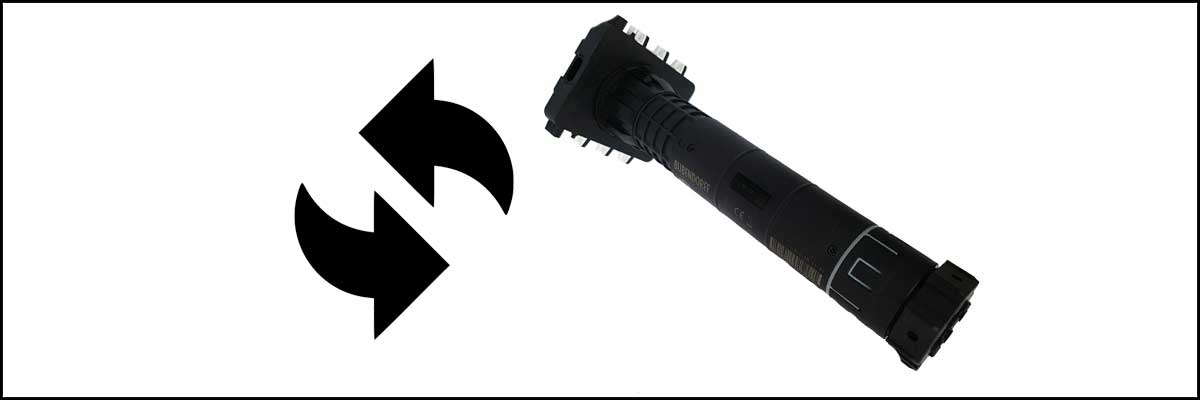
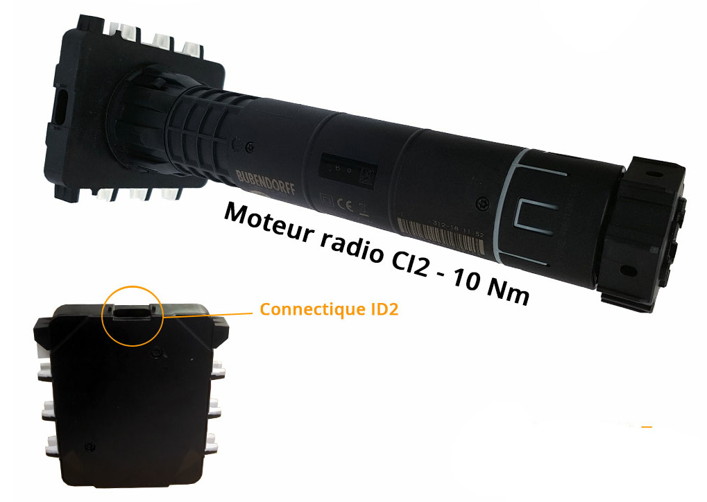
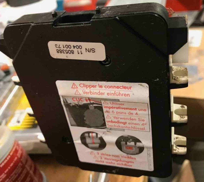
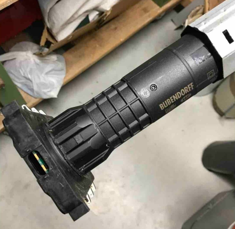
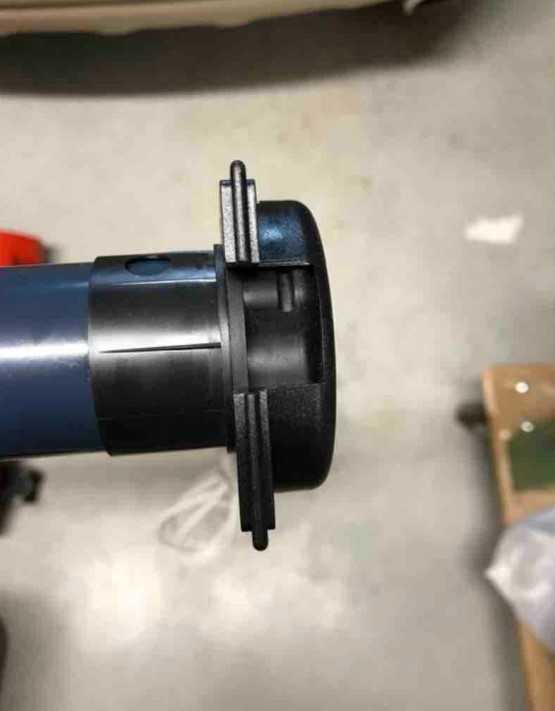
How do I know if my Bubendorff motor is from the ID2 range and that I can therefore follow this tutorial?
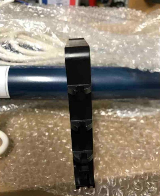
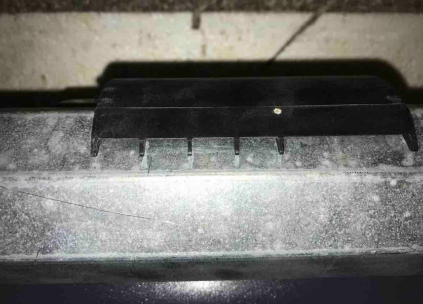
Your engine will need to look like this model:
How to replace a Bubendorff motor from the ID2 range with a Somfy?
Thanks to our client, Victor MORIM, who made a complete report to create this user manual. If you have additional advice, write to us at contact@lacentrale-eco.com
Before you begin, consider:
- Lower the roller shutter all the way down
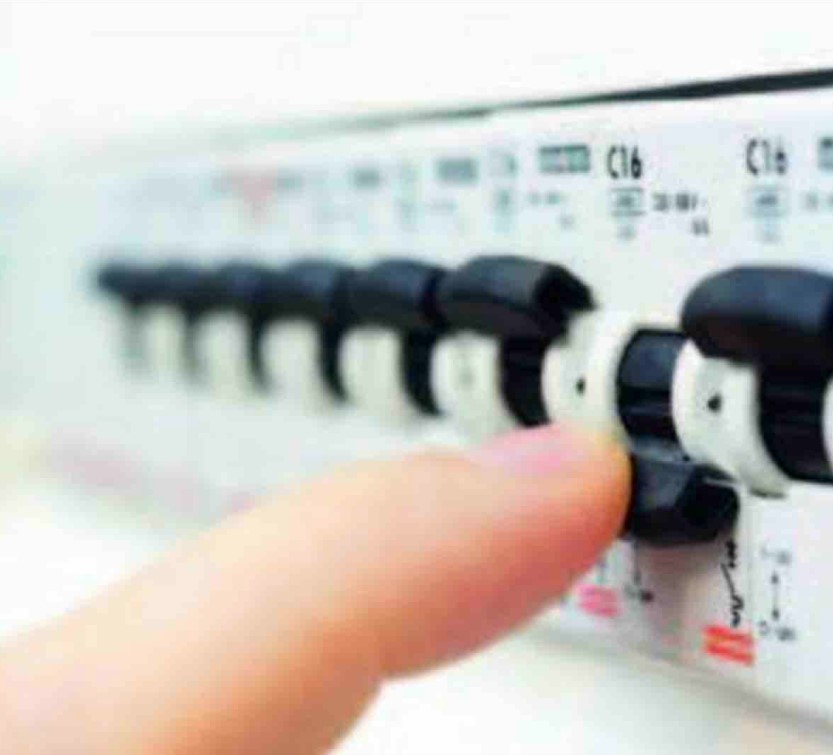
- Turn off the power to the shutter at the circuit breaker
- Depending on the type of shutter, remove the underside to access the shaft of the roller shutter
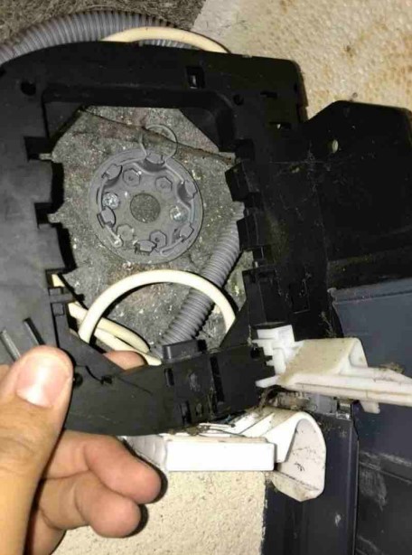
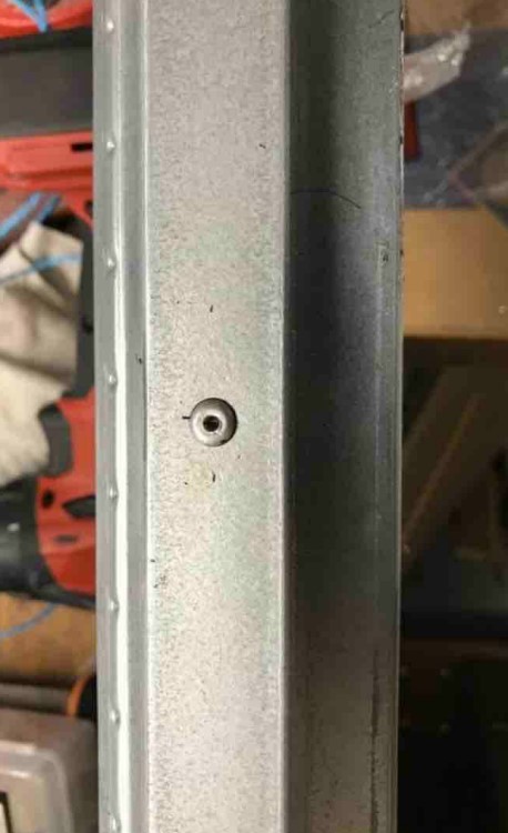
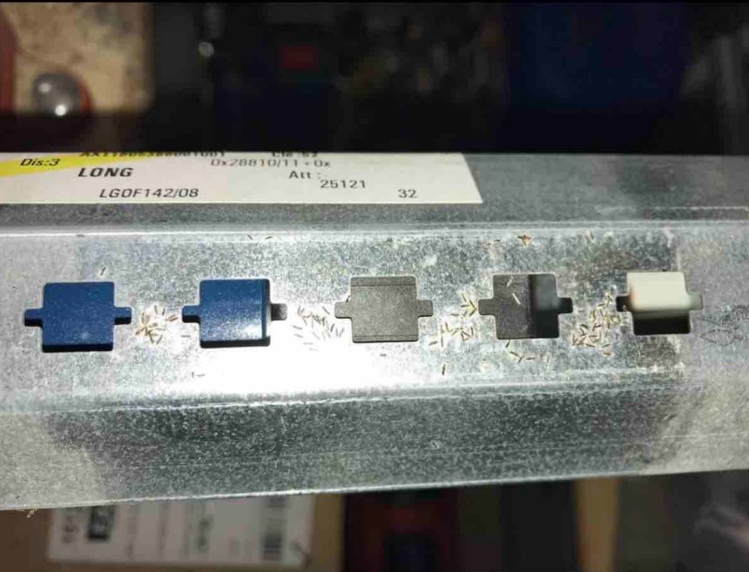
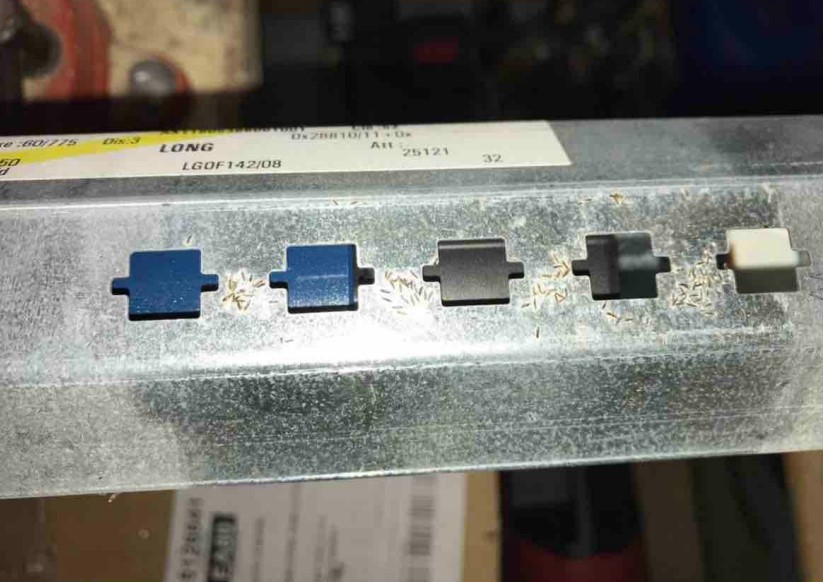
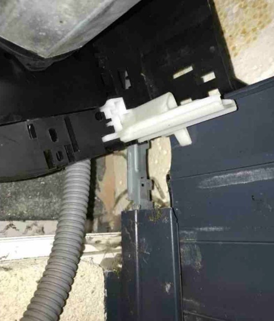
1. Access to the first apron attachment or automatic lock (also serving as a limit switch)
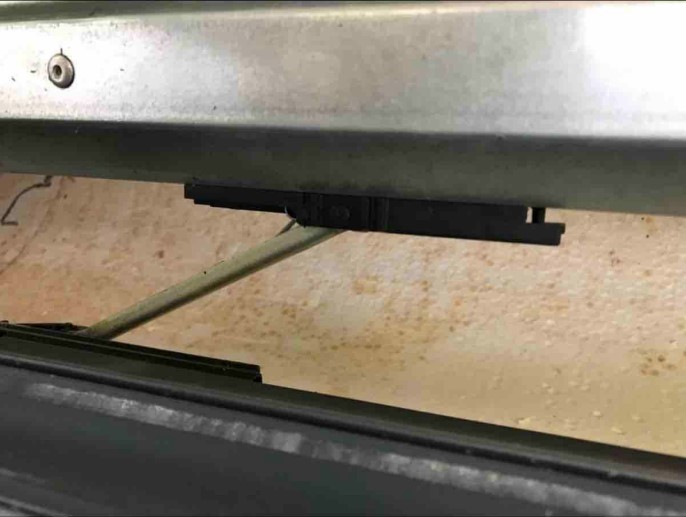
2. Access to the second apron attachment or automatic lock (also serving as a limit switch)
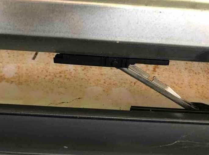
3. Fastener unhooked, the pin is released
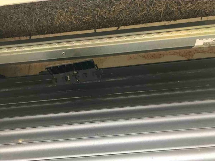
4. Same for the other fasteners
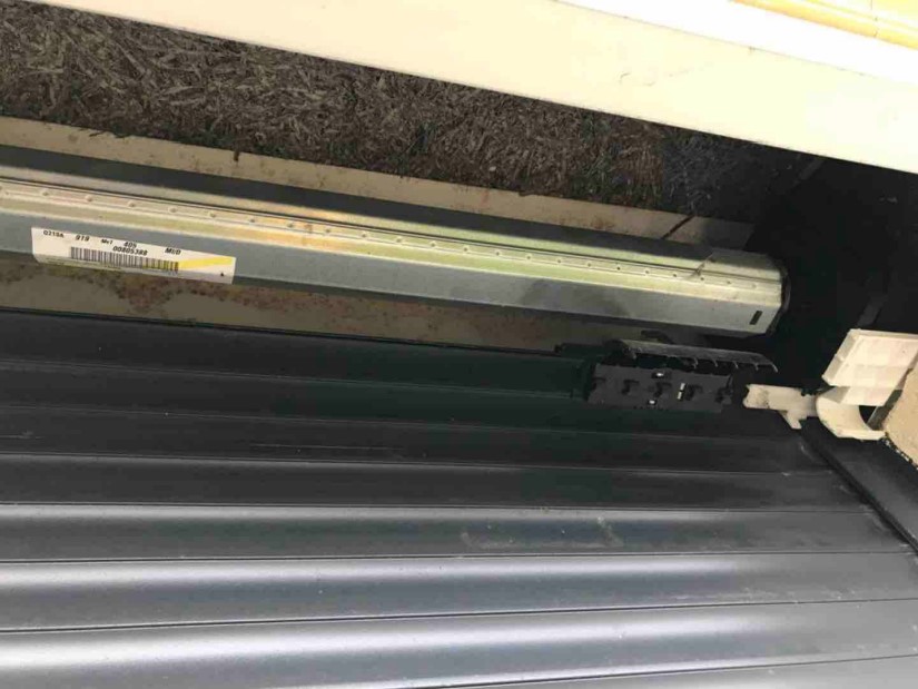
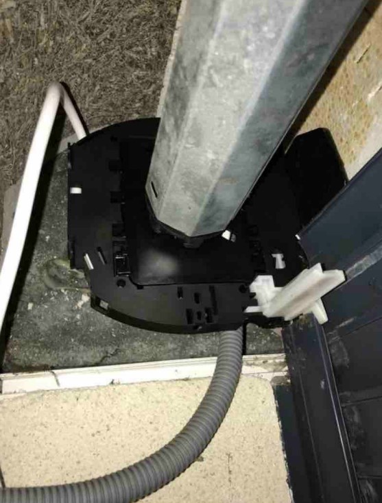
5. Unclipping the axle support on the side opposite the engine (tandem side)
du Somfy-3" class="cp-lazy" src="/images/blog/replacing-motor-Bub-by-Somfy/image-replacing-motor-bubendorff-by-somfy/p8.jpg?1632843459366" style= "display: block;" />
6. Following the unclipping of the axle support on the side opposite the engine (tandem side)
7. Removal of the axle support, non-engine side (tandem side)
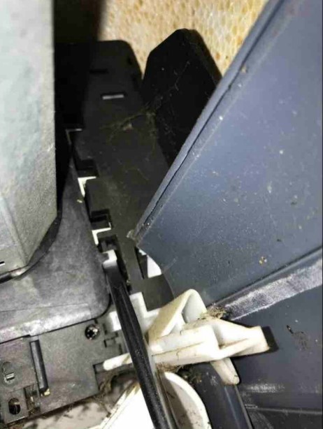
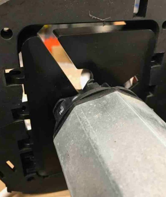
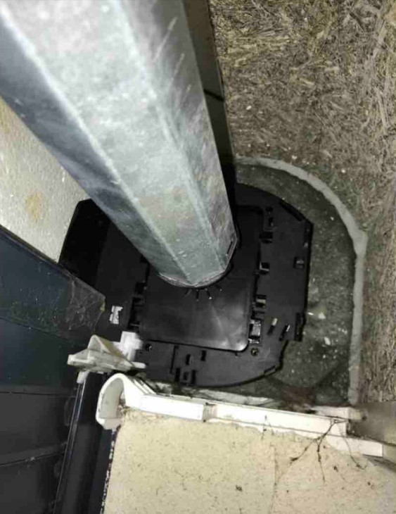
8. Unclipping the axle support, motor side
9. Following unclipping of the axle support, engine side
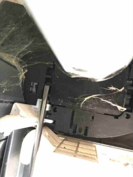
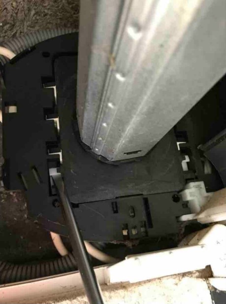
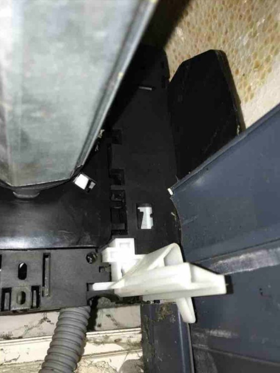
10. Removal of the side panel clipped onto the slide (motor side)
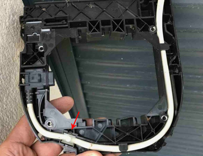
11. Unclip the centering tab to release the side panel (motor side)
12.
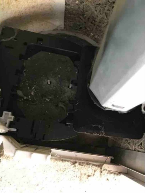
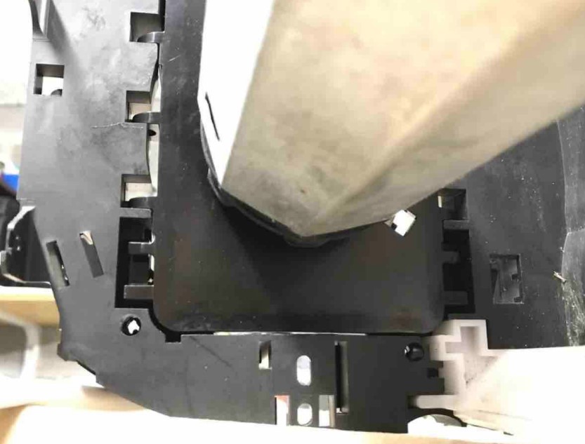
13. Cheek removal
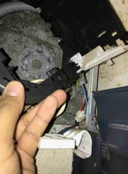
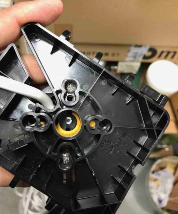
14. Removal of the power cable from the old Bubendorff motor. It is advisable to carefully disassemble the white clip at the bottom left to reuse it
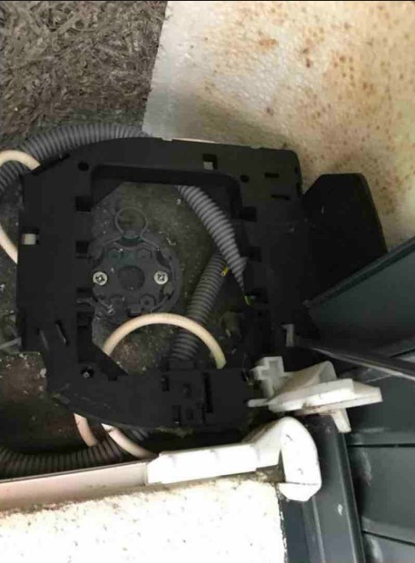
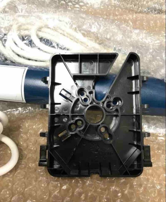
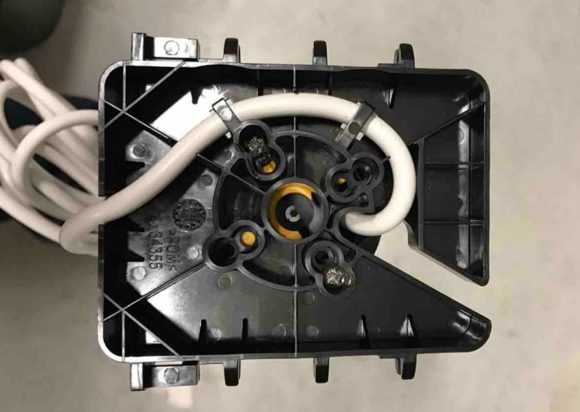
15. Panel ready for adaptation of the new Somfy roller shutter motor
12" class="cp-lazy" src="/images/blog/replacing-motor-Bub-by-Somfy/image-replacing-motor-bubendorff-by-somfy/p18.jpg?1632843623697" style="display: block;" />
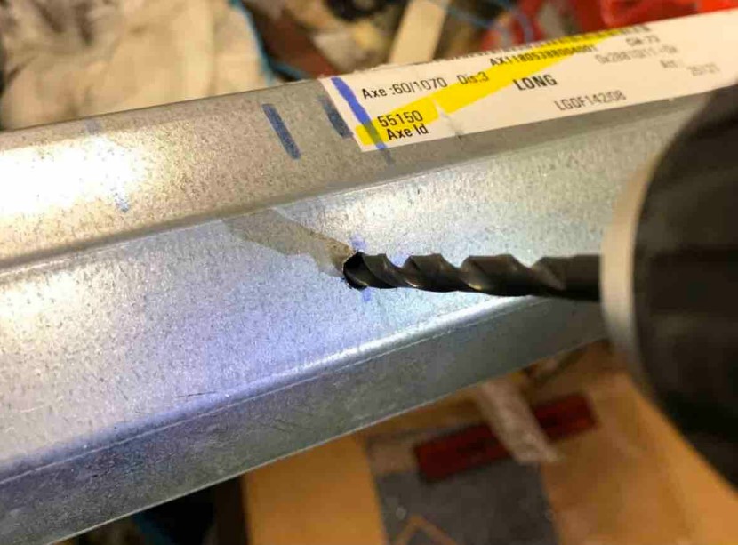
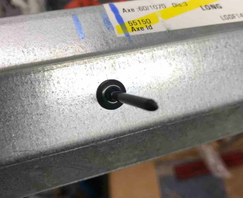
16. Bubendorff motor to be removed from the axle
17. To free the axle, remove it or the rivets, using an HSS Ø5 bit
18. Once the rivet(s) are removed, you can take out the Bubendorff engine
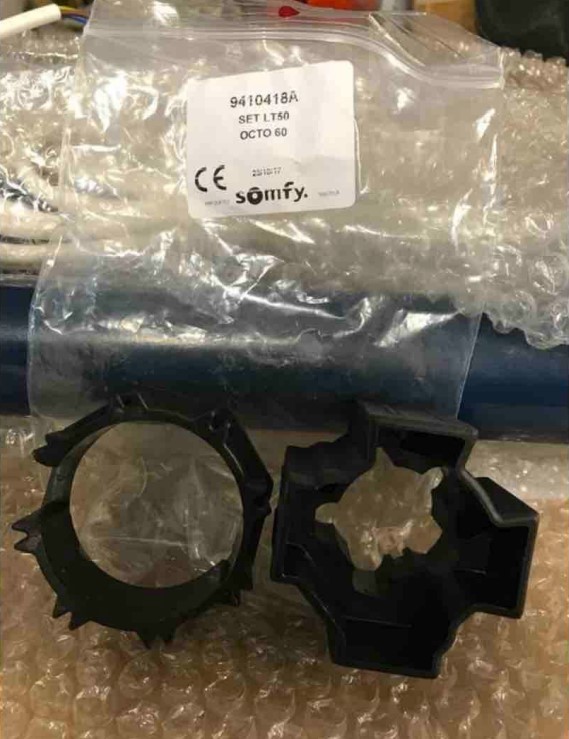
19. For this step, the materials needed are:
- SOMFY IO motor , with the motor torque adapted to your roller shutters.
- If necessary, LT50 wheel and crown for SOMFY motor adaptation on octagonal shaft Ø 60 mm from Bubendorff.
It is provided when you buy a new engine
20. Materials also needed:
- Tradi Titan ID2 radio axis support , to install a SOMFY motor on a Bubendorff flange
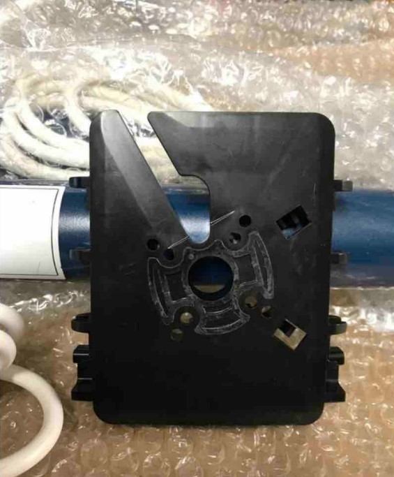
21. The same support, seen from the side (available on https://lacentrale-eco.com/fr/ accessoires/axe-fr/support-daxe/support-daxe-tradi-titan-id2-radio-somfy-la- pair-bubendorff.html )
22. The same axis support
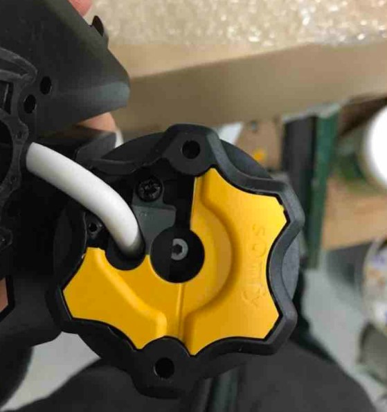
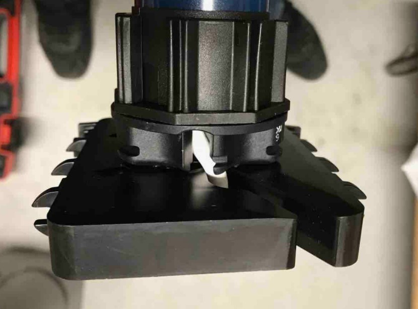
23. Prepare the SOMFY motor by positioning the cable on the side, in the notch provided.
Then cut the piece of yellow plastic to the right of the cable
Ulant Bubendorff by Somfy-20" class="cp-lazy" src="/images/blog/replacing-motor-Bub-by-Somfy/image-replacing-motor-bubendorff-by-somfy/p26.jpg?1632843705311 " style="display: block;" />
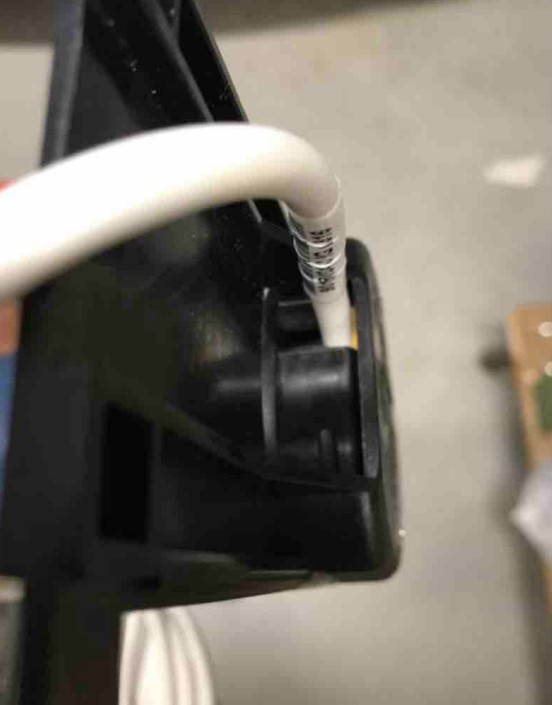
24. Here is the cable when it is pre-positioned, with the plastic cut correctly
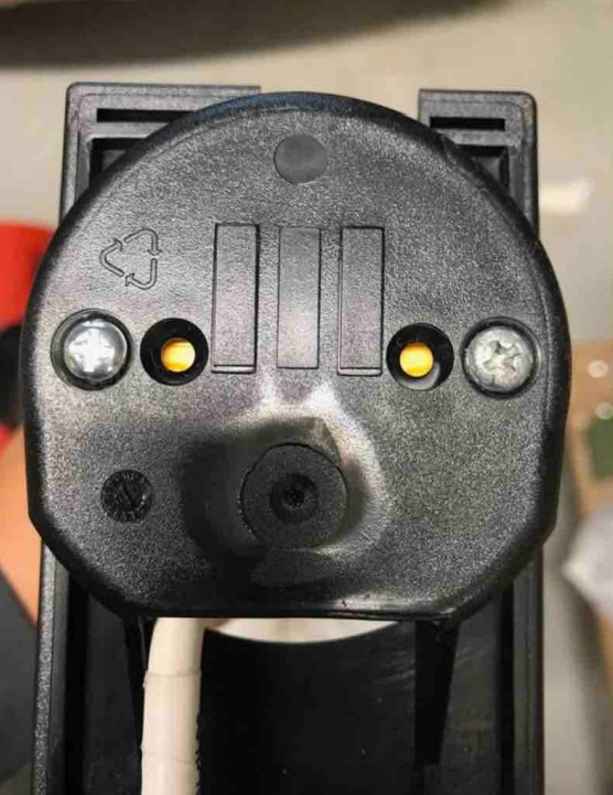
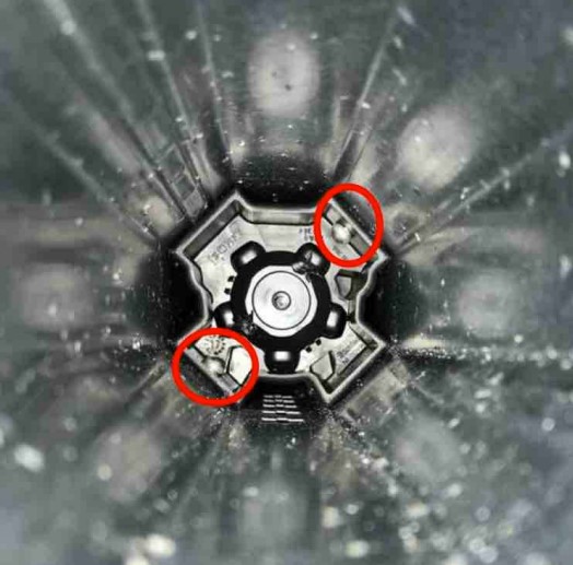
25. Position the outer holes of the ace support opposite the 2 corresponding reservations of the engine
26. Assembly of the engine on the ace support using 2 sheet metal screws 4.8x12, pan head PZ2.
Note that it may be necessary to shorten the length of the screw
27. Passage of the cable in the recesses provided for this purpose at the rear of the axle support
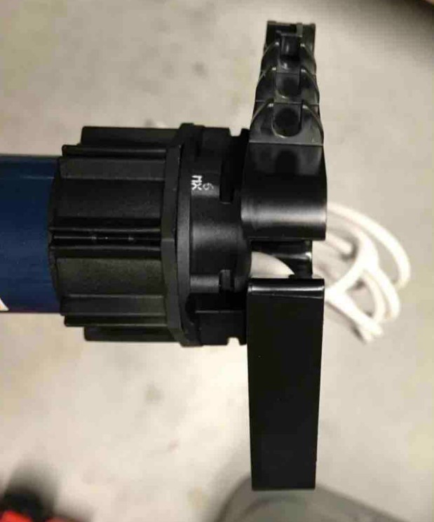
28. Motor and axis support ready to be assembled on the existing axis
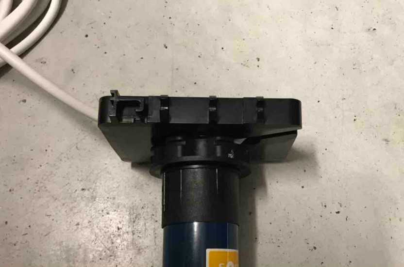
29. Motor and axis support ready to be assembled on the existing axis
30. Motor and axis support ready to be assembled on the existing axis
31.Motor and axis support ready to be assembled on the existing axis
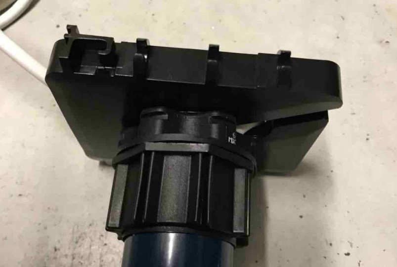
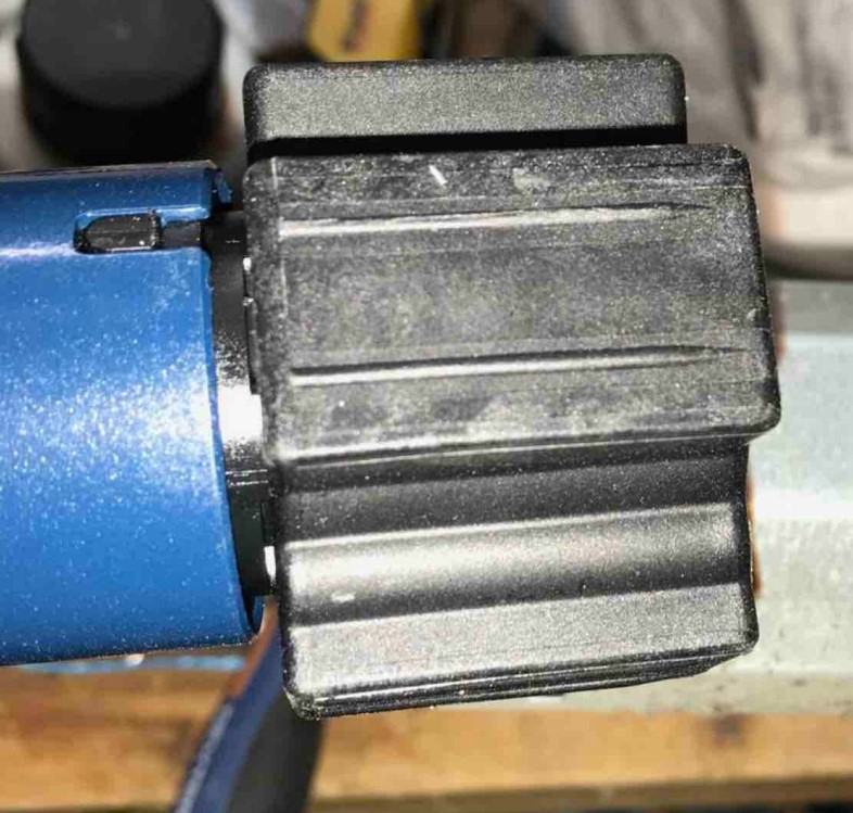
32. In this photo, you can clearly see the axis adaptation crown. It was slipped into the body of the Somfy motor
ur-bubendorff-by-somfy/p35.jpg?1632843834670" style="display: block;" />
Either you have an ID2 cheek of this type: https://lacentrale-eco.com/ accessoires/caisson-et- accessoires/joues/joues-mono-id2-motor-ca-roulement- exterieur-bubendorff.html or this guy https://lacentrale-eco. com/accessories/housing-and-accessories/cheeks/cheeks-tradi- id2-motor-ci-g-bubendorff. html
and it will be necessary to take the reference:
Either you have a block drawer side of this type:
https://lacentrale-eco.com/ accessoires/caisson-et- accessoires/joues/joue-200- standard-bloc-bubendorff.html or this type https://lacentrale-eco. com/accessories/housing-and-accessories/plays/plays-172- standard-block-bubendorff.html
and it will take this model:
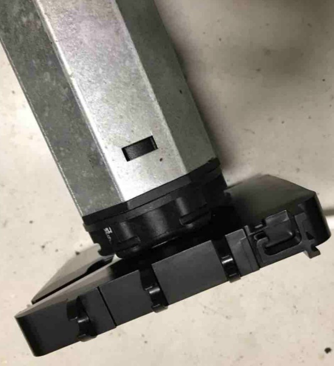
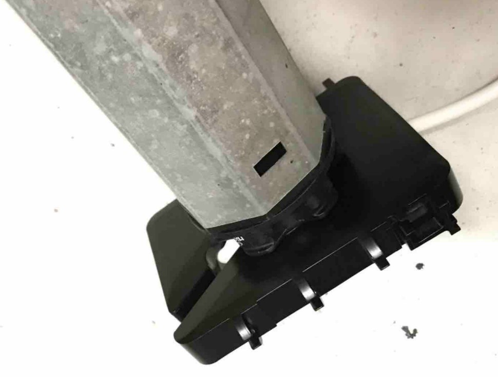
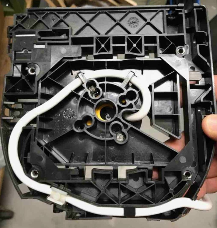
33. Assembling the SOMFY motor the SOMFY radio block N/R drawer. Find the drawer on Lacentrale-eco
34. Assembly of the SOMFY motor on the SOMFY radio N/R block drawer
35. Assembly of the SOMFY motor on the SOMFY radio N/R block drawer
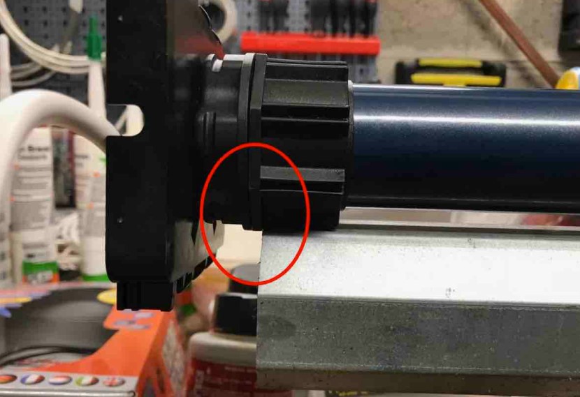
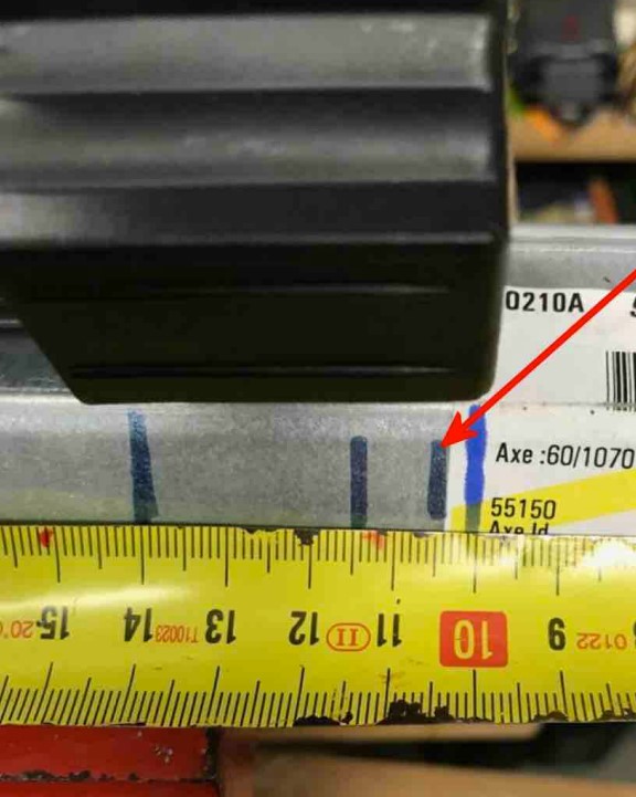
36. To determine where to drill to assemble the new motor and the existing shaft, placethe engine exactly as in the photo
38.
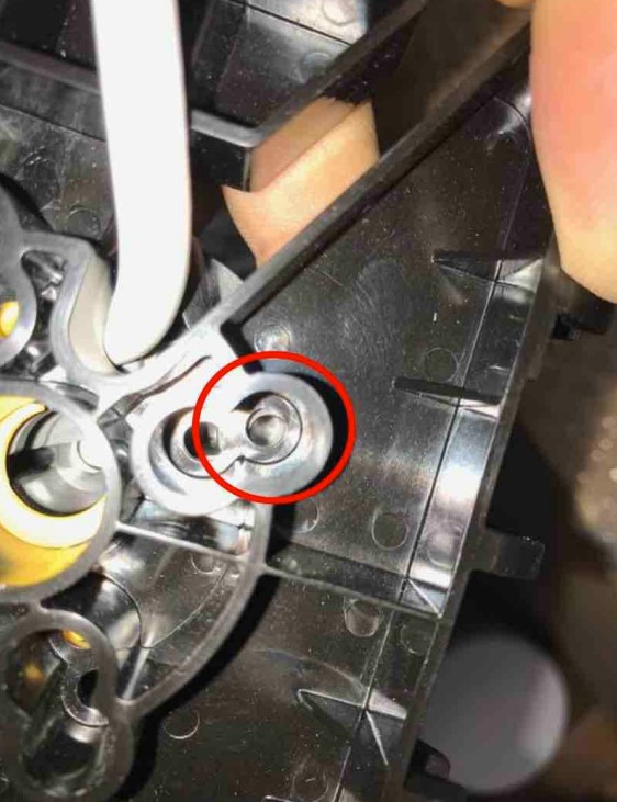
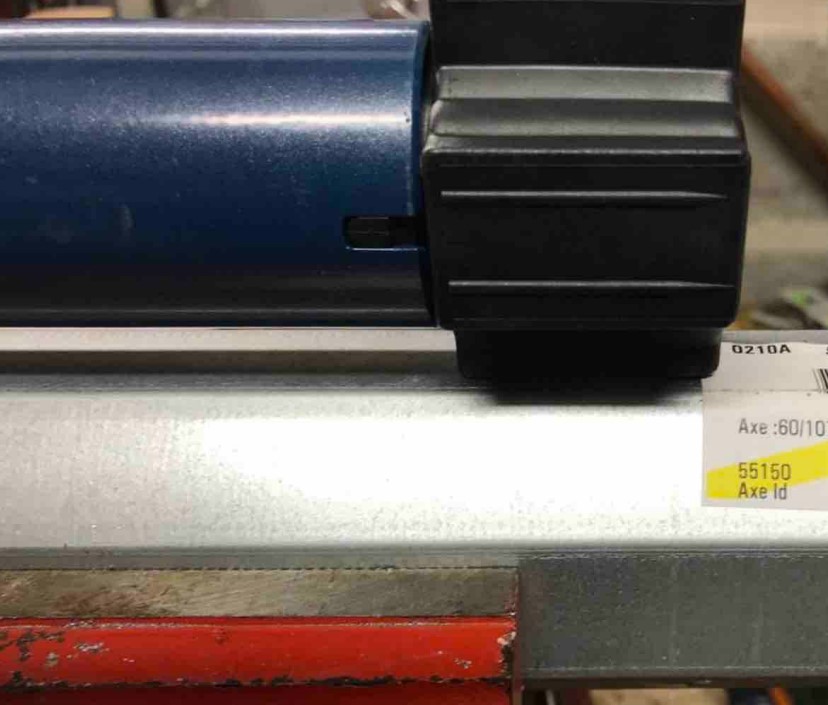
39. Here is the place to drill, according to the SOMFY instructions
40. Note: when the flaps are not very wide, be careful not to slip the motor in the axis as in the photo.
The adaptation wheel, thus positioned, will prevent the refitting of the apron fasteners (or automatic locks)
41. The adaptation wheels are designed to have different positions in the axis, to position it correctly.
42. Correct positioning of the wheel and the motor, test that it is possible to reposition the fastener of part 1) to be certain that everything is ok
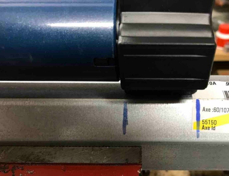
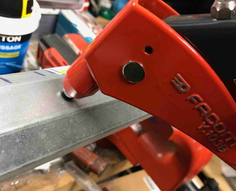
43. Drilling the axle and the wheel with an HSS Ø5 or Ø4.8 drill bit
44. Installation of 1 or 2 rivets 4.8x12 (one in front of the other, on either side of the axis)
45. Laughveteran
46. Properly set rivets
47. New SOMFY motor block/shaft support and Bubendorff roller shutter shaft assembled
48.
49. Positioning of the assembly in the cheek previously prepared in step 15
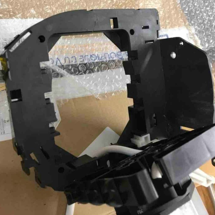
50.
51.
52. Correct clipping
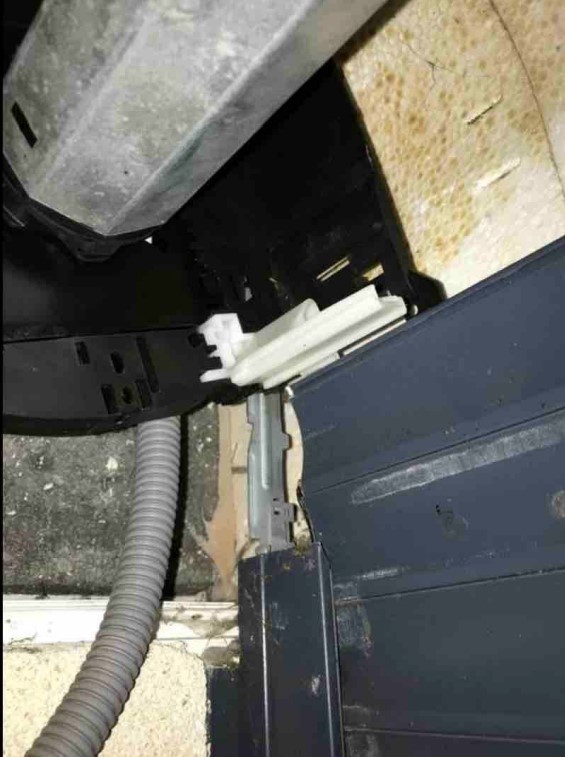
53. Positioning of the new motor cable and white clips repositioned on the cheek
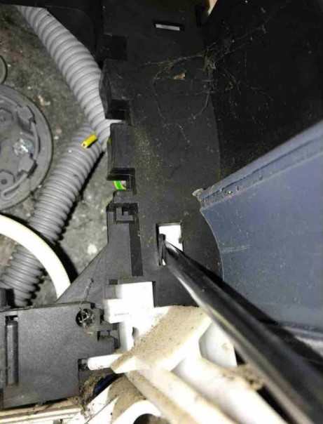
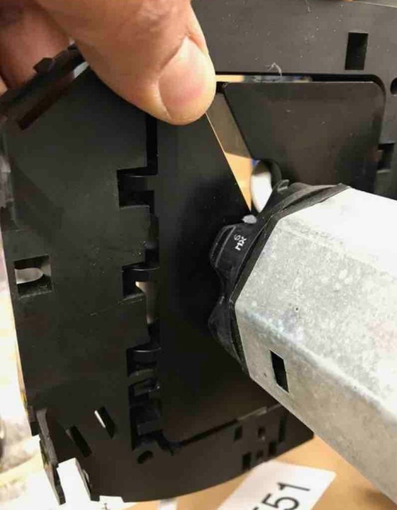
54. Rest the new assembly on the flap, pass the cheek well in my centering tab of the engine side slider
55.
56. Once the plastic lug is properly clipped into the metal tab, refitting is correct
57.
58. Refitting with clipping of the axle support in the cheek on the tandem side, side opposite the engine (remained in place)
59. Refitting the apron fasteners or automatic locks (also serving as a limit switch)
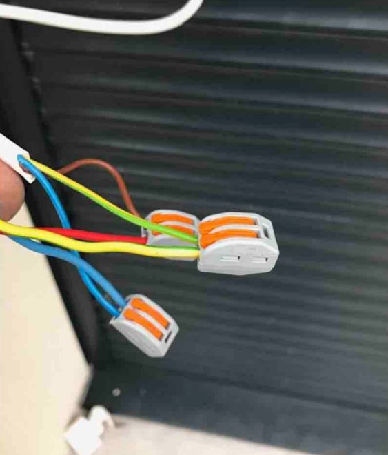
60. Electrical connection of the new motor
61. Return circuit breaker to service. Then make the adjustments necessary for the proper functioning of the new motor, according to the SOMFY instructions
In case of doubt about the assembly, we are at your disposal to accompany you.
Contact us if you have any doubts.
Good editing!


